Refurbishing an old Edison Motor
I bought an old motor that was manufactured as a fan motor by the Edison Manufacturing Company over 100 years ago.
The motor is a Gramme Ring type. Supposedly, these went out of style because of low efficiency, but as a practical matter, they are harder to manufacturer than today's dc machines because the armature wire has to be threaded through the ring to make up the coils.
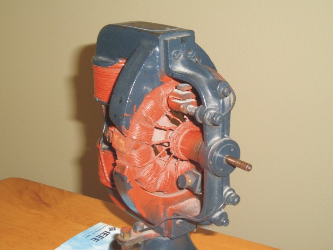
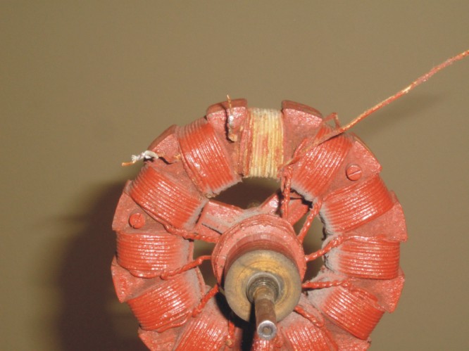
This picture shows the motor as I got it. Someone had painted the motor black and the windings red, but not done a good job at it. Also, the brushes are completely missing, so I will have to make new ones.
Here is a close up of the initial motor.
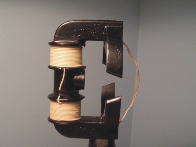
First, I removed the field winding. There were 97 turns on the field. That is 48.5 on one coil and 48.5 on the other. The wire measured 70 thousandths (0.07 inches) in diameter which roughly equates to 13 AWG.
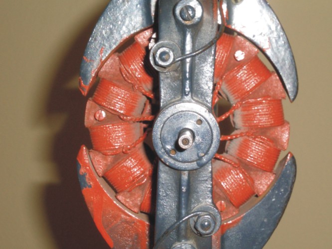
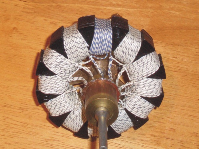
Here is a close up of the rotor.
Next, the armature winding was removed. There were 40 turns in each slot (arranged in 4 layers of 10 turns). The armature wire measured 35 thousandths which is roughly equivalent to 20 AWG.
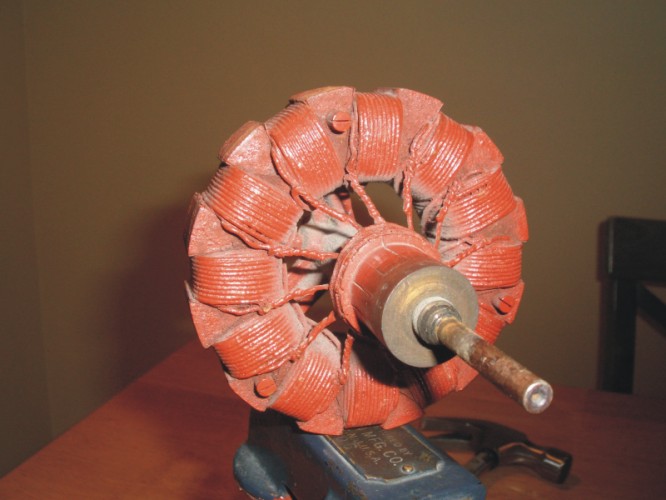
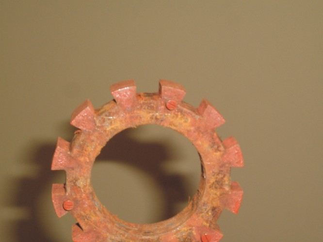
Here is the armature ring with no windings.
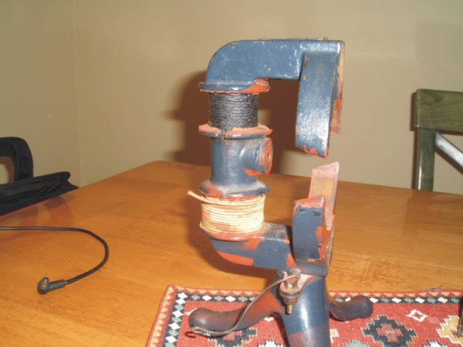
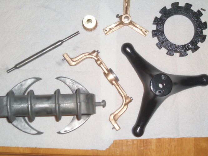
Next, I put all the parts in a sand blaster, then polished them with a Dremel tool. Something I didn't expect is that the front piece and the Y shaped piece at the back of the armature turned to a gold color after the paint was removed. So, I painted them with clear paint to preserve the original color. In the picture below, they are their original colors. The other parts were a grey steel color as shown by the stator piece in the bottom left of the picture. I ended up painting these parts black as shown by the stand and armature ring in the right side of the picture. The commutator and shaft (in the upper left) were left as is and coated with oil.
Now, its time for rebuilding. The picture below shows the armature with four windings added. Although I used 24 AWG wire, the insulation was much thicker than the original wire. I also used tape instead of plastic protectors in the slot which took up less room, but still, the windings were much bulkier than the original.
The completed rotor is shown below. I soldered the rotor coils to the commutator bars even though they weren't with the original motor. I ran out of white/black wire and used blue/white wire for one coil. The armature resistance measured 0.2 ohms from one bar to the next.
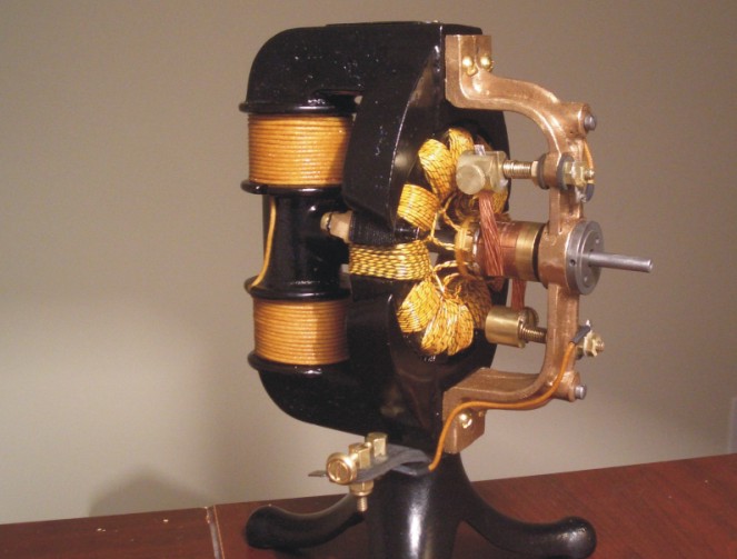
The stator with a new winding is shown below. Since I wanted to use cloth coated wire, I had a limited selection. As it turns out, the wire I used for the rotor and stator had a much smaller diameter, but heavier insulation, than the original wire. I wound approximately the same number of turns as the original motor. I think the only limitation will be on the current. However, I don't have the fan attached, so the motor will run no-load. The field resistance measured 0.6 ohms.
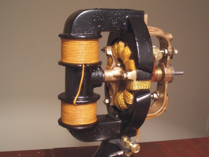
Below is the assembled motor. I replaced the screws on the front with brass screws since one of the original ones was missing. The original screws seemed to be #7.5-32 so I tapped them out to #8-32. I made brushes out of copper wire, but I will replace these with better ones later. I also varnished the windings with amber shellac. This holds the wire in place, but also makes the windings look better because they are not bright white anymore.
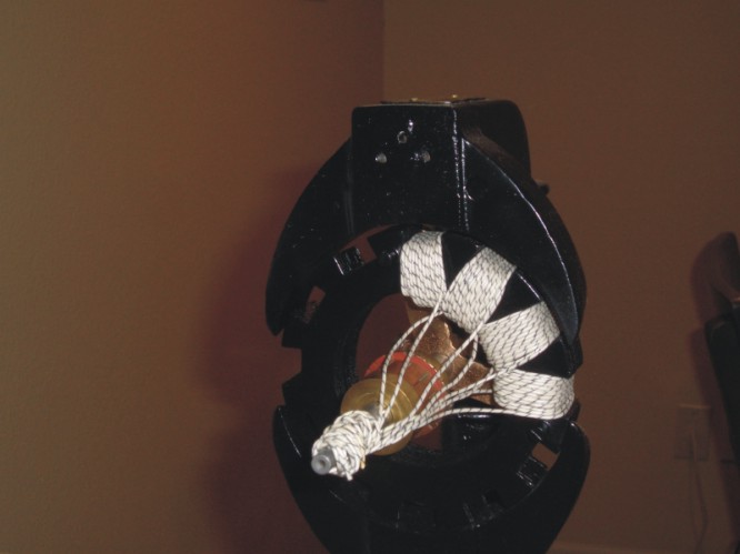
When looking at the back of the motor, I realized that I put the Y shaped piece in backwards. It doesn't really matter, but the rotor would have been easier to wind if the piece was in correctly. The original motor had two weights mounted to the back of the Y piece. I put these back on and went through a balancing procedure to reduce the vibration.
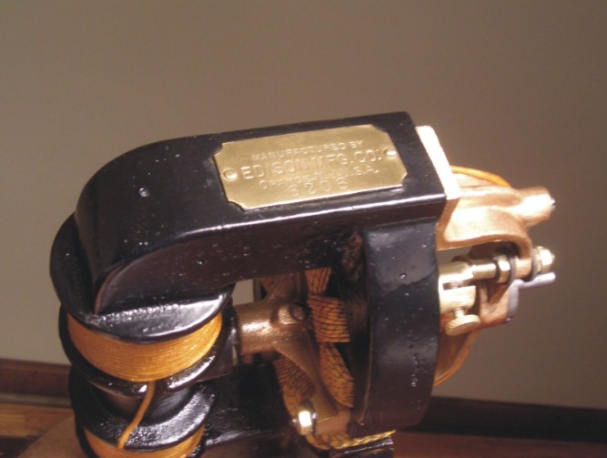
Here is the motor from the top where the label shows the serial number. It is 6206.
Below is a video of the motor running from a 6V power supply. It draws about 4 amps at start-up and about 1.5 amps when running.
Other than making better brushes and getting a permanent power supply, the re-building is finished.